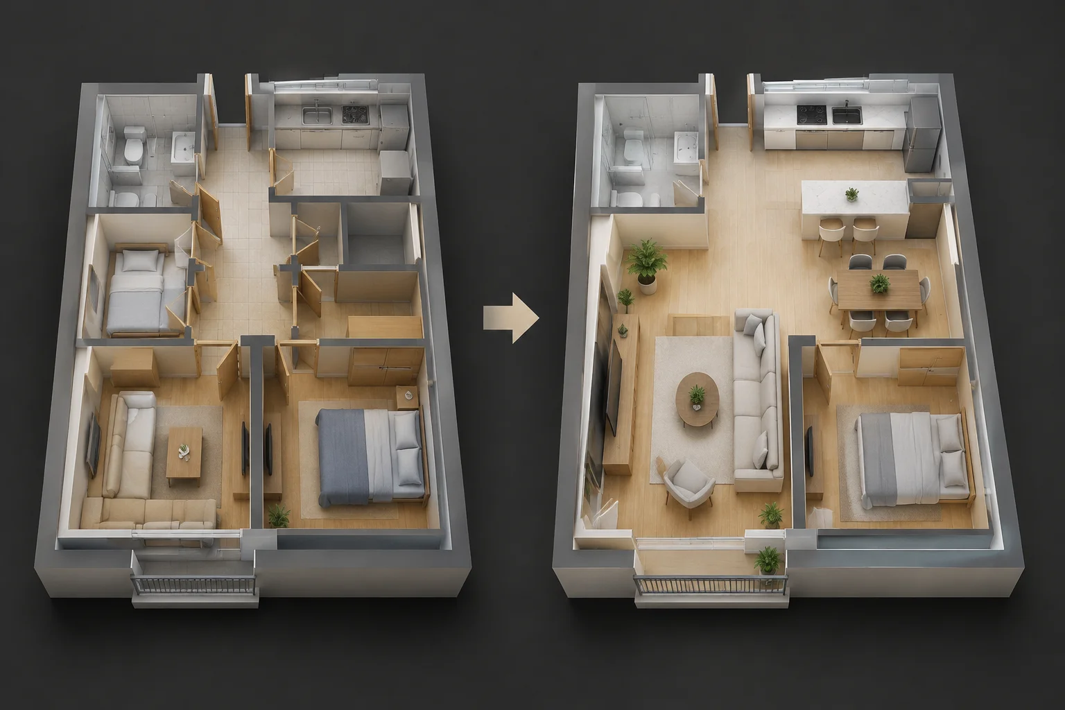
The Friction of Uncoordinated Comparative Layouts
Renovation proposals rely heavily on showing clients and municipal authorities how spaces transform from their baseline state to their proposed configuration. When reviewers examine existing floor plans alongside proposed arrangements, their eyes naturally scan for static structural benchmarks like elevator cores, perimeter exterior walls, and primary structural column grids. An unexpected shift in drawing origins or an inconsistent graphic weight between views immediately creates spatial confusion.
Documentation teams frequently stumble when maintaining two independent CAD drafts or unlinked drawing models for before and after layouts. Changes made to existing perimeter walls during site survey updates fail to filter into proposed plans. The resulting discrepancies undermine contractor confidence, distort gross internal area comparisons, and generate conflicting quantity takeoffs during early cost estimating stages.
Shared Coordinate Origin Requirement
Before generating before-and-after presentations, lock the project base point and internal origin across all documentation sheets. Never adjust drawing view crop boundaries arbitrarily to fit title blocks; always employ synchronized Scope Boxes to guarantee that column grids occupy the exact same coordinate positions on every sheet.
Structuring Parallel Phased Floor Plans in Revit
Autodesk Revit manages sequential reality through a unified element timeline. Instead of duplicating geometry into separate project files, every element belongs to a single building information model while carrying explicit life-cycle metadata: Phase Created and Phase Demolished. To create a pristine existing conditions plan, the view phase must be set to Existing with the phase filter assigned to Show Complete. This hides future demolition cuts and reveals only what stood on site at the initial surveying pass.
When an architectural team compares two functional eras of a building, discrepancies do not originate from geometry alone; they stem from conflicting phase temporal boundaries.
— Thomas Grid, Senior Architectural Technologist
Constructing the matching after plan requires the view phase parameter set to New Construction. Choosing the filter Show Previous + New suppresses the dashed demolition debris while showing existing structures alongside new drywall assemblies, modern glazing systems, and refreshed MEP penetrations. Both views look into the very same geometry database, ensuring that an adjusted exterior brick thickness immediately reflects across both sheets without duplicate manual drafts.
The Automatic Infill Wall Pitfall
When a door or window in an existing wall is demolished in a subsequent phase, Revit automatically injects a small wall segment to patch the void. Verify that this infill adopts the phase parameters of the host wall; otherwise, unwanted seam lines will appear in your proposed elevation and plan presentations.
Common Discrepancies, Automatic Infills, and Partition Creep
Cross-checking before and after plans requires rigorous audit checks across subtle model behaviors. Discrepancies rarely appear as catastrophic layout misalignments; rather, they slip into documents through microscopic detailing glitches that compound across multi-story buildings:
- Structural Core Continuity: Load-bearing shear walls and perimeter columns must display unchanged material cross-hatching across both drawing sets. Any change in hatch pattern implies demolition or structural intervention where none was intended.
- Door Swing and Clear Opening Parity: Check that egress clearances remain compliant between existing historic frames and new commercial entries, confirming that the demolition of old frames does not leave invisible boundary artifacts.
- Room Tag Boundary Confinement: Room separation lines generated in the Existing phase frequently bleed into the New Construction phase, producing ghosted boundary warnings or distorting calculated rentable square meterage.
- Curtain Wall Mullion Alignment: When historic storefronts transition into modern high-performance thermal envelopes, thermal break lines and glass centerlines must correspond to established grid dimensions rather than arbitrary rough openings.
Protocol for Error-Free Sheet Layout Assembly
For executive presentations and statutory submissions, arrange both floor plans on the exact same drawing sheet. View titles should align along an identical baseline, and viewport crops must remain pinned. When municipal officers compare room transitions, they can trace horizontal sightlines from the left Existing view straight across to the right Proposed layout without hunting for rotated North arrows or mismatched scale ratios.
Dual-View Quality Assurance Checklist
Before publishing final plot files, activate a temporary red-line overlay in your PDF viewer or drafting software to superimpose both sheets. Zero drift should occur across primary structural grids, party walls, and vertical utility shafts.