Methodological guide on isolating preserved heritage stone envelopes, sequencing lateral steel shoring, and staging new floor plate tie-ins in Autodesk Revit.
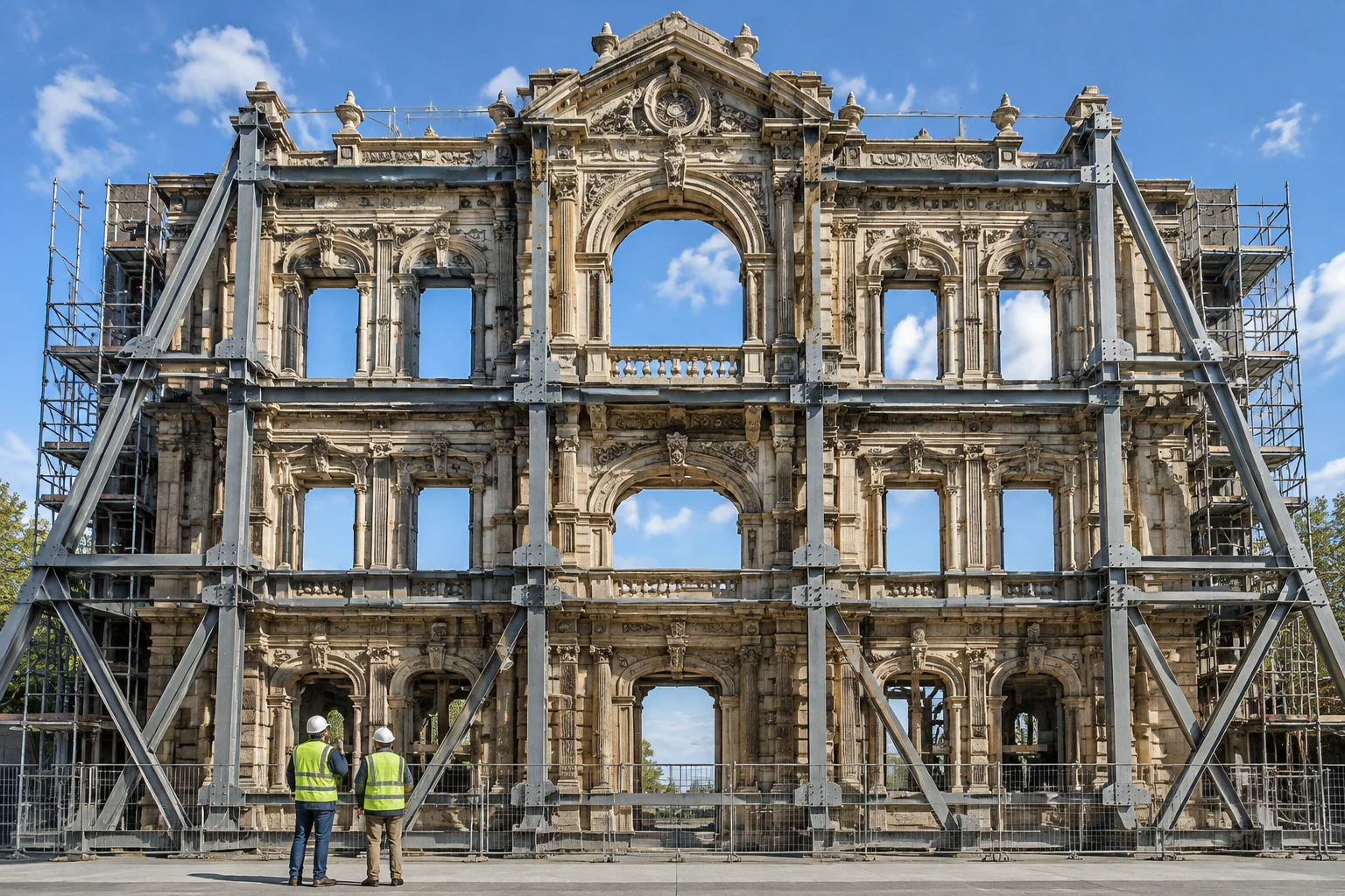
Steel retention bracing towers securing the landmarked exterior ashlar facade during interior structural demolition.Phase 01 Preserved • Phase 02 Demo
Phasing Breakdown & Matrix Sequence
Preserving a nineteenth-century masonry facade while gutting the interior floor plates demands an uncompromising phase separation. In Autodesk Revit, modelers frequently err by treating the entire original perimeter as a single compound wall assembly, which contaminates material takeoffs and confuses phase created and phase demolished boundaries.
When the perimeter wall belongs to the existing phase and must endure intact through demolition and new construction phases, every interior structural connection must be severed cleanly inside the BIM database. This case study details how to define the retention boundaries, assign temporary steel whalers, and track concrete slab insertion without corrupting scheduled quantities.
01Envelope Demarcation & Dual-Wall Separation
In heritage retention projects, the stone facade never changes its lifecycle status: its Phase Created parameter is set to 'Existing' and its Phase Demolished remains strictly 'None'. However, the interior floor joists, cross-bracing partitions, and roof trusses framing directly into masonry pockets are tagged for demolition. If you model composite walls where structural backup and ornamental ashlar masonry are fused into one multi-layer Revit wall family, pocket demolitions will inadvertently carve voids across your exterior elevation drawings.
The solution is a dual-wall strategy. Split the exterior masonry into two parallel modeled elements: the outer continuous envelope assigned purely to the Existing phase, and the inner bearing liner or framing pocket boundary. By disallowing joins between the outer facade and the inward floor framing, demolition filters display the floor removal without generating false graphic voids across the street elevations.
Phasing Integrity Note
Never utilize in-place voids on an Existing wall to simulate floor removals if the void is created in a New Construction phase. Doing so forces Revit to calculate a demolished sub-component, potentially misreporting masonry mass in Phase Demolition schedules.
02Intermediate Shoring Phase & Load Transfer
Once the existing internal structure is flagged as Demolished in the demolition phase, exterior lateral stabilization becomes urgent. Temporary steel shoring trusses and raking whaler beams must exist in the model to document clear clearances for excavators and piling rigs. Because these shoring towers are installed before interior demolition and dismantled only after the new concrete core cures, their lifecycle spans intermediate phases.
Phasing is not just a chronological timeline; it is a topological contract between retained mass and transient support mechanisms.
In Revit, create a distinct phase titled 'Temporary Shoring' positioned immediately between 'Existing' and 'Demolition'. Assign the steel towers Phase Created = 'Temporary Shoring' and Phase Demolished = 'New Construction'. This sequence guarantees that shoring appears highlighted in demolition views, remains visible in foundation excavation drawings, and vanishes automatically from final handover sheets without manual view-hiding overrides.
03New Superstructure Tie-In & Graphic Filters
The final stage introduces new reinforced concrete floor slabs anchored into the historical brickwork using chemical dowel pins. Documenting this requires careful phase filter discipline. A custom Phase Filter named 'Show Preservation & New' must be configured with Existing set to 'Overridden' (light halftone with solid grey poche) and New Construction set to 'By Category' (heavy vector contours with dark hatch).
Temporary Shoring Towers: Phase Created = Shoring Phase, Phase Demolished = New Core
Slabs & Tieback Pins: Phase Created = New Construction, Phase Demolished = None
This graphic segregation instantly clarifies to structural estimators where brand-new concrete meets historic brick. Any junction lines between new cast-in-place slabs and retained stone are maintained cleanly without graphic merging, preventing false construction joints in shop drawings.
Documentation Desk
PhaseState Team
Technical BIM Research Desk
The PhaseState Editorial Desk synthesizes architectural phasing standards, building lifecycle matrices, and graphic override conventions for intricate commercial and conservation projects.
04Frequently Asked Phasing Inquiries
Cutting an Existing wall with a Wall Opening whose Phase Created is Demolition causes Revit to treat the entire host masonry zone as altered, generating unwanted graphical outlines on exterior elevation drawings. Modeling an independent inner face liner preserves pristine exterior lines.
By assigning the shoring components Phase Demolished = New Construction, standard Phase Filters like 'Show Complete' in New Construction views automatically suppress the shoring geometry without requiring manual 'Hide in View' workarounds.
Yes. In your Wall Material Takeoff, set the view phase to Existing and filter by Phase Demolished equals None. Combine this with material description filters to prevent newly specified grout or ties from inflating existing heritage stone totals.
Consultation & Review
Inquiring About Complex Renovation Phasing?
Consult with our technical team for guidance on multi-phase project setup, temporary work staging, and graphic override matrix design.